|
|
|
|
|
|
|
|
|
|
|
|
|
|
|
|
|
|
|
|
|
|
|
|
|
|
|
|
|
|
|
|
|
|
|
|
|
|
|
|
|
Super DX-5
1930
Norden-Hauck, Inc.
Engineers
NW Corner of Delewar Ave. and South St.,
Philadelphia, Pennsylvania, USA
|
|
|
|
|
|
|
|
|
|
|
|
|
|
|
|
|
|
|
|
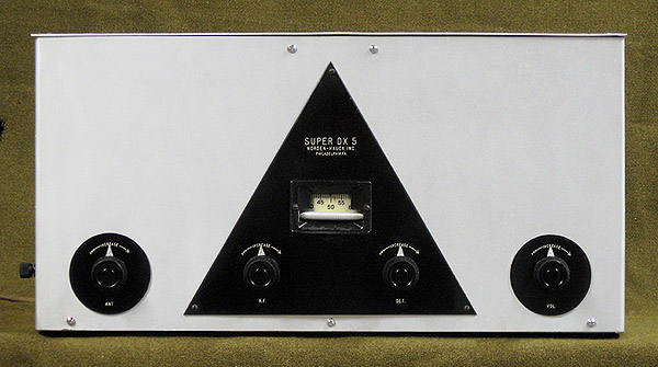
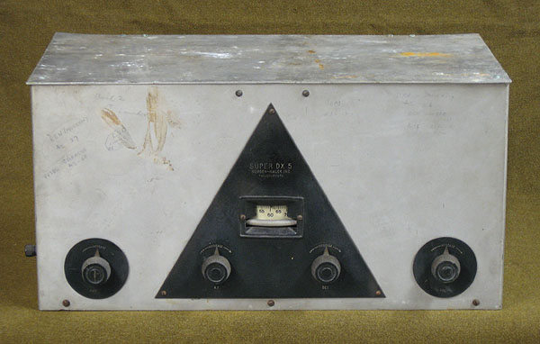
The Super DX-5 was Norden-Hauck's answer to short wave listening
in 1930. It was designed to be a fully, self contained, SW receiver with
band switching capabilities by means of plug in coils. It's a Screen
Grid TRF/Regenerative receiver that was designed to compete against the
Pilot "Super Wasp", the Silver Marshall "Around the World Wide 4", the
National SW-1 and SW-2 sets, the ICA "Challenger" and other shortwave
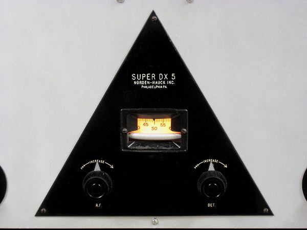
receivers of that time. The front controls consist of a vertical tuning
dial, antenna control, RF. and Det. trimmers, and a regeneration
control. The regeneration control acts as the volume control but can
also act as the BFO for listening to SSB when it's turned high enough to
allow the set to go into regeneration. When listening to SSB, the
antenna control can be used as the volume control. The RF. and Det.
trimmers can be used to fine tune the desired frequency for the best SSB
audio. On the bottom cover plate is stamped with the serial number
A113. It was a common practice to start a serial number with 100 or 1000
in order to give a false indication of greater production then what
there actually was. If this is the case with this set, and I believe it
is, then that would make this the 13th receiver that Norden-Hauck made.
It's believed that these receivers were only made during the first half
of 1930.
I acquired this receiver in August 2013 by trading a
McMurdo Silver 18 inch concert speaker for it. I believe this receiver
is one of only three receivers that are known to exist.
|
|
|
|
|
|
|
|
|
|
|
|
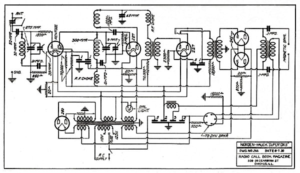
Tube Line Up:
CeCo AC Pentode.....RF Amplifier
27.....Detector
27.....Preamplifier
45 X 2.....Audio Output
80.....Rectifier
|
|
|
|
|
|
|
|
|
Power Source:
AC...120 Volts
|
|
|
|
|
|
|
|
|
Frequency Range:
LW.....100 kHz - 550 kHz
BC.....550 - 700 kHz / 700 kHz - 1600 kHz
SW1.....1.5 MHz - 3 MHz
SW2.....7 MHz -15 MHz
SW3.....3 MHz - 7 MHz
SW4.....15 MHz - 25 MHz
|
|
|
|
|
|
|
|
|
|
|
|
|
|
|

|
|
|
|
|
|
|
|
|
|
|
|
|
Dimensions:
Height.....9 inches
Width.....19 inches
Depth.....10 inches
|
|
|
|
|
|
|
|
|
|
|
|
|
|
|

|
|
|
|
|
|
Address location on Google Map.
|
|
|
|
|
|
|
|
|
|
|
|
|
|
|
|
|
|
|
|
|
|
|
|
|
|
|
|
|
|
|
|
|
|
|
|
|
|
|
|
|
|
|
|
|
|
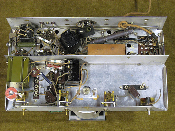
This is the underside view of the chassis prior to restoration.
Upon close examination, there was considerable evidence that this
receiver had been serviced before, possibly during the 1930s. There was a
number of resistors and wires that were poorly soldered in place, and
in some examples, there were connections that were totally void of any
solder. One of the Grey and white "dogbone" resistors that fed the B+
voltage to the 27 audio tube was supposed to have a value of 12K ohms
but it actually measured 120K ohms. This means that , at some point in
time, there was a production run of 120K ohm resistors which were
mislabeled as 12K ohm resistors and one of these resistors made it's way
into the production of this particular receiver, thus, drastically
reducing the audio quality of the first audio stage. It's hard to say if
any of the other DX-5 receivers were affected in this way but it's
quite possible. There's also the possibility that the 120K ohm resistor
was the correct one to use and the schematic diagram is wrong. Either
way, in the restoration of this receiver, I decided to replace the 120K
ohm resistor with a NTE brand 12K ohm 2 watt metal film resistor. In the
overall restoration of this receiver, half of the resistors were
bypassed by 2 watt metal film resistors and all of the paper capacitors
were bypassed by modern NTE filter capacitors and moden bypass
capacitors.
|
|
|
|
|
|
|
|
|
|
|
|
|
|
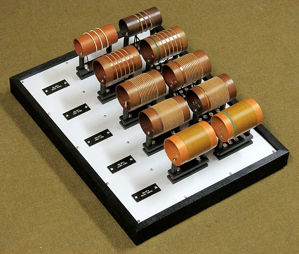
Below is the set of coils that came with my DX-5. The three
large coil sets make up the standard set of coils that were to accompany
every DX-5 that was originally sold. Each coil set is numbered on the
bottom of their bases and their designated tuning ranges are as follows:
Coils #1.....7 MHz to 15 MHz
Coils #2.....3 MHz to 7 MHz
Coils #3.....1.5 MHz to 3 MHz
The smaller coil is one of a set of coils (it's companion
coil is currently missing) that was designed to tune 15 MHz and above.
It was an additional set of coils that was to be purchased separately.
Coils #0.....15 MHz to 25 MHz
There was a set of coils ,to be purchased seperatly,
which covered the BC and LW band. The BC coils could change thier tuning
ranges by means of a switch and a capacitor which were attached to
them.
Coils #4.....550 to 700 kHz / 700 kHz to 1600 kHz
Coils #5.....100 kHz to 550 kHz
|
|
|
|
|
|
|
|
|
|
|
|
|
|
|
|
|
|
|
|
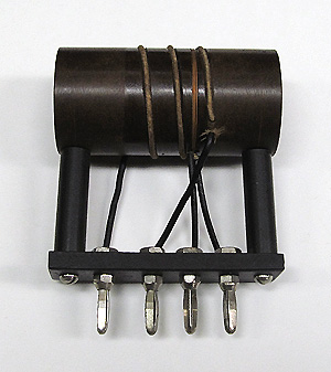
Coils #0.....15 MHz to 25 MHz
Coil Form.....Length 3 inches / Width 1.5 inches
Primary Coil......2.75 turns of 16 gauge silk covered solid core wire.
Regenerative Coil..... 4 turns of 30 gauge silk covered solid core wire.
I only have this one coil of what's supposed to be a
matched set of coils. I plan of making a complete set of reproduction
coils for this frequency range.
|
|
|
|
|
|
|
|
|
|
|
|
|
|
|
|
|
|
|
|
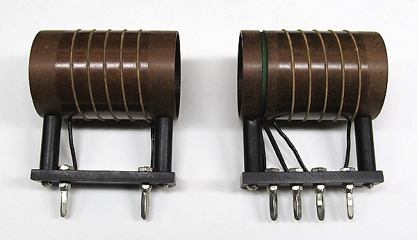
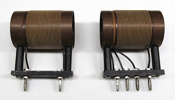
Coils #1.....7 MHz to 15 MHz
Coil Form.....Length 3 inches / Width 2 inches
Primary Coil......5 turns of 18 gauge silk covered solid core wire.
Regenerative Coil..... 6 turns of 30 gauge silk covered solid core wire.
|
|
|
|
|
|
|
|
|
|
|
|
|
|
|
|
|
|
|
|
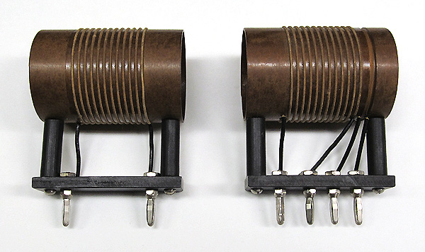
Coils #2.....3 MHz to 7 MHz
Coil Form.....Length 3 inches / Width 2 inches
Primary Coil......12 turns of 18 gauge silk covered solid core wire.
Regenerative Coil..... 5 turns of 30 gauge silk covered solid core wire.
|
|
|
|
|
|
|
|
|
|
|
|
|
|
|
|
|
|
|
|
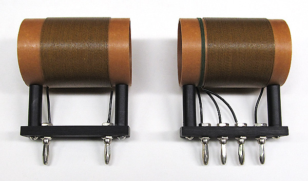
Coils #3.....1.5 MHz to 3 MHz
Coil Form.....Length 3 inches / Width 2 inches
Primary Coil......28 turns of 20 gauge silk covered solid core wire.
Regenerative Coil..... 6 turns of 30 gauge silk covered solid core wire.
|
|
|
|
|
|
|
|
|
|
|
|
|
|
|
|
|
|
|
|
Coils #4.....540 to 700 kHz / 700kHz to 1500 kHz
Coil Form.....Length 3 inches / Width 2 inches
Primary Coil......64 turns of 22 gauge silk covered solid core wire.
Regenerative Coil..... 6 turns of 30 gauge silk covered solid core wire.
Because my receiver never came with a set of #4 BC coils,
I had to reproduce them. The bases were made from a salvaged 1920s
bakelite radio panel that I acquired from fellow collector Alan Douglas.
Their surfaces were lightly scraped with fine sandpaper in order to
mach the dull matte finish that the original coil bases had. The
standoffs were made from two plastic 1/2 inch standoffs which I glued
together, cut down to 3/4 inches in length, sanded and painted matte
black to match the look and texture of the original standoffs.The banana
plugs were purchased from MAI/Prime Parts of Indianapolis, the
Garolite coil forms were purchased from the McMaster-Carr Supply Company
of Elmhurst, Illinois, the 22 gauge vintage silk covered wire was
purchased on Ebay, and the 30 gauge silk covered wire was salvaged from a
salvaged 1930s radio IF coil. Spegettie tubing was used to cover the
wire leads from the coil to the contacts.
|
|
|
|
|
|
|
|
|
|
|
|
|
|
|
|
|
|
|
|
I made this coil rack in a style that I thought would closly
match the styling of the receiver. The base is made of Ash, which was
painted black, and the panel was made of aluminum which was bead blasted
to match the aluminum surface of the receiver.
|
|
|
|
|
|
|
|
|
|
|
|
|
|
|
|
|
|
|
|
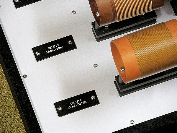
The frequency range ID plates were engraved at a local trophy
shop. They had a plastic that had a surface that exactly matched that of
bakelite. Each coil has it's own socket which makes coil removel
and insertion easy.
|
|
|
|
|
|
|
|
|
|
|
|
|
|
|
|
|
|
|
|
|
|
|
Citizens Radio & Call Book Magazine and Technical Review
Winter 1930, Page 151
|
|
|
|
|
|
|
|
|
|
|
|
|
|
|
|
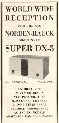
The above ad
shows the DX-5's early design. Only one RF trimmer is featured and it's
located above the dial. This design lasted only a few months in 1930
before the design was changed to feature two RF trimmers which are
located below the dial.
|
|
|
|
|
|
|
|
|
|
|
|
|
|
|
|
|
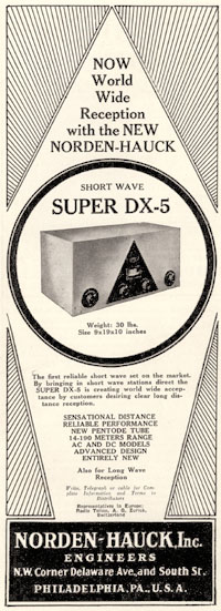
Citizens Radio & Call Book Magazine
Winter 1930, Page 100
|
|
|
|
|
|
|
|
|
|
|
|
|
|
|
|
|
|
|
|
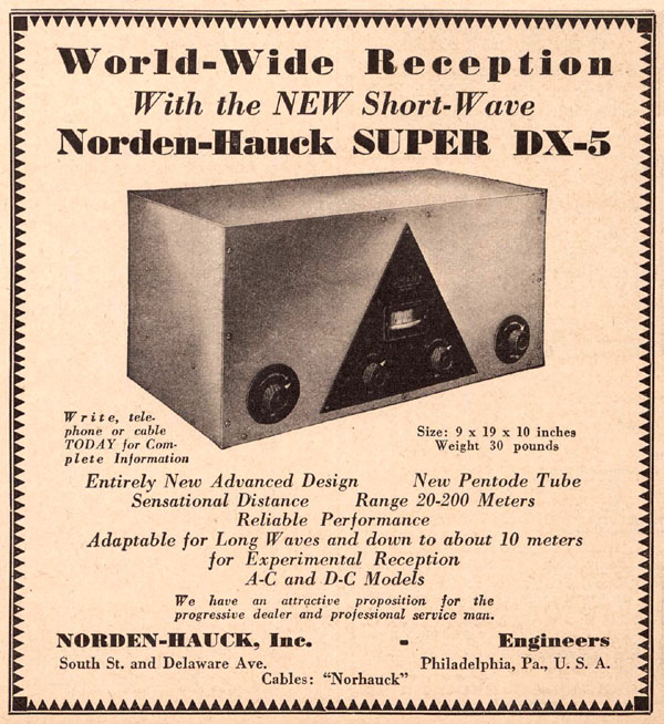
Radio News, December 1930
Page 559
|
|
|
|
|
|
|
|
|
|

|
|
|
|
|
|
|
|
|
|
Norden Hauck DX5 Designed For Quiet AC Operation
Following
is a description of the Super DX-5 receiver, a recent commercial
development, by Norden Hauck, Inc., giving the points of particular
interest to the short leave enthusiast. This receiver was designed with
the following points in mind: complete a.c. operation without hum,
increased sensitivity and selectivity, ease of control and ability to
hold calibration, good tone quality and sufficient power output, and
ability to cover a wide frequency range. The completed set has fulfilled
these points with a high degree of satisfaction.
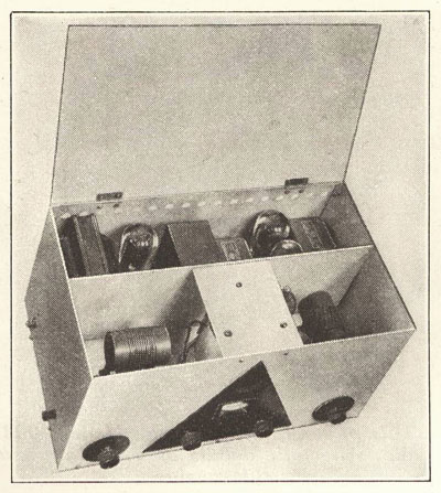
The accompanying photograph shows the type of
construction employed resulting in an efficient set that is fairly
compact (9 inches high, 18 inches long, 10 inches deep), and one that
has an appearance of which the owner may be justly proud.
A power transformer, with three 2.5 volt secondaries, has
resulted in the suppression of those tunable hums that are encountered
on the higher frequencies. Each secondary has a 20 ohm center tap
resistance shunted across it with the centertap connected to ground.
These resistances are located right at the respective sockets and the
grounds are made to the common point for that stage. Grid and plate
wires do not run near the resistance, hence no pick-up of hum.
AVOIDING PICKUP
The antennae binding post is on the left side of the set,
near the front, which position was chosen to avoid coupling between the
antennae lead-in and the power supply. One side of the line is grounded
through ½ microfarad condenser. Inserting the power supply plug in the
light socket so that the ungrounded side of' the line is connected to
this condenser usually results in the quietest operation. A type 80 tube
is used as rectifier for the plate supply. The speaker is connected by
plugging into a new type of socket similar to a UY socket but with an
extra prong which controls a switch closing the field terminal contacts
when the speaker is removed. In this set the switch is so connected that
when the speaker is removed a 500 ohm resistance is connected in place
of the field winding resulting in no change in voltage and eliminating
the possibility of damaging the set by high voltage. The set may also be
operated with a magnetic speaker with the plug removed with a slight
increase in hum. It is intended however that a choke coil be plugged in
when the dynamic speaker is not used.
USING RF PENTODE
The use of a tuned radio frequency incorporating, a
pentode tube provides a marked increase in sensitivity and selectivity.
At frequencies lower than 10,000 kilocycles the gain obtained from a
pentode tube was noticeably greater than that obtained from a screen
grid lobe. The extra gain is not obtained from the pentode tube unless
the tube is worked at its maximum plate potential, that is 250 volts.
When the pentode is worked at l80 volts plate potential the gain over a
screen grid tube is hardly worth while. The greatest gain was obtained
when the detector coil was used as a tuned plate impedance.
NO BODY CAPACITY
The design of the Super DX-5 is such that there is no
hand capacity effect oil even the highest frequencies. This has been
accomplished by complete shielding and by doable shielding between the
contents and the front panel. As can be observed in the photograph there
is an inner shield upon which the antenna coupling condenser, the radio
frequency compensating condenser, the detector trimmer condenser and
the regeneration condenser are mounted. These controls are grounded on
this shield, except for the antenna condenser, and are insulated from
the front shield. This prevents all currents from flossing in the front
shield. The two main tuning condensers are mounted on the same shaft and
mounted in the set in a vertical position with a knurled aluminum drum
dial projecting through the panel. The vertical mounting results in a
minimum of friction and equal pressure on the bearings giving smooth and
noiseless operation coupled with great ease of adjustment. An
illuminated celluloid scale enables accurate logging and serves as a
pilot light. The radio frequency compensating condenser provides a ready
means for lining up the radio frequency stage and compensating for
changes in capacity produced by variation of the antennae coupling
condenser.
The detector trimmer condenser provides a fine tuning
adjustment equivalent in 1.80 degrees adjustment to from one to three
degrees on the main tuning dial.
Variation in the radio frequency compensating condenser
has only a slight effect upon the tuning of the detector stage, not
enough to lose the beat note of a signal, and the detector trimmer
condenser provides a ready means to bring the detector in line again.
For amateur band reception the main tuning control can be set at
predetermined points and all the tuning done with the lower controls.
The regeneration control is noiseless and very smooth in operation and
has only a slight effect on tuning so that when reduced to stop
oscillation for reception of a modulated signal the readjustment is
tuning will never be greater than a slight change of the detector
trimmer condenser and usually none at all is needed.
CHART FURNISHED
An individual calibration chart is furnished for each set
and when the tubes are supplied this calibration is made with the tubes
that are to be used. An accuracy of 1 per cent or better is obtained
and due to the rigid construction of coils and set there is very little
change in use. This tuning chart is of great advantage to the newcomer
to the short wave field as it enables him to locate the stations desired
or identify the stations heard in spite of the tremendous span of
frequencies covered.
TONE QUALITY
No sacrifice in tone quality was made in lieu of more
difficult means of reducing hum. Low ratio high quality audio
transformers are used with two type 45 tubes and a dynamic speaker
enabling an output to be obtained which in audio range and undistorted
power equals the standard set by the finest broadcast receivers. There
are plenty of short wave phone signals oil the air which with an
efficient set will supply enough power to load up push pull 45's. A
headphone jack is provided which taps in the plate of the first audio
stage, cutting out the loudspeaker, or if desired phones may be
connected to the magnetic speaker terminals.
Standard equipment includes three sets of coils, six
coils all. which cover a range of from 1500 to 15,000 kilocycles with
generous overlap between coils. Extra coils can be obtained to cover
from 15,000 to 25,000 kilocycles. For reception in the ordinary
broadcast band coils may be obtained which cover from 540 to 700 to 1600
kilocycles in two steps by means of a switch provided on the base of
the coil which cuts in an auxiliary condenser for the lower frequencies.
On special order coils can be provided to cover from 100 to 550
kilocycles, two sets of coils being used. When operating on frequencies
lower than 550 kilocycles an adjustable tickler is provided on the coil
and a .005 fixed condenser is shunted across the regeneration condenser.
Citizens Radio Call Book and Technical Review
September 1930
Pages 52 and 108
|
|
|
|
|
|
|
|
|
|
|
|
|
|
|
|
|
|
|
|
Citizens Radio Call Book and Technical Review, September 1930
Page 52
|
|
|
|
|
|
|
|
|
|
|
|
|
|
|
|
|
|
|
|
Citizens Radio Call Book and Technical Review, September 1930
Page 52
|
|
|
|
|
|
|
|
|
|

|
|
|
|
|
|
|
|
|
|
|
|
|
|
|
|
|
|
|
|
|
|
|
|
|
|
|
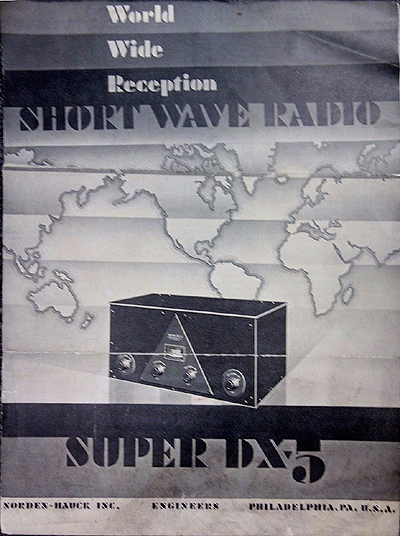
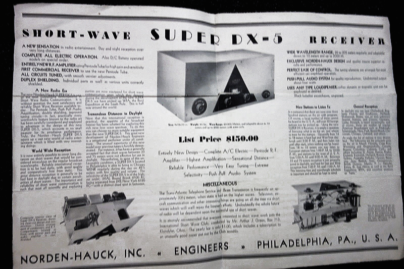
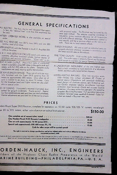
These photos of an origional brochure were taken off of an Ebay auction.
|
|
|
|
|
|
|
|
|
|

|
|
|
|
|
|
|
|
|
|
|
|
|
|
|
|
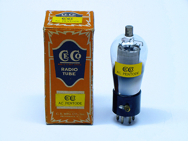
CeCo "AC Pentode" radio tube which was also designated as the
"P-1". The box was origionally labled for a 201A tube but was updated
with AC Pentode lables. Inside the box is the origional wool packing
material. Even though this is a NIB tube, I don't ever plan to use it in
my receiver for fear of possibly damaging it. The 24 tube that's
already in my receiver works great. I acquired this tube in May 2017.
|
|
|
|
|
|
|
|
|
|

|
|
|
|
|
|
|
|
|
|
|
|
|
|
|
|
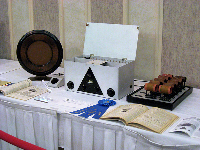
2014 ARCI "Radiofest" Radio Contest Entry - Operating
There is an extra set of BC coils plugged in the receiver.
|
|
|
|
|
|
|
|
|
|

|
|
|
|
|
|
|
|
|
|
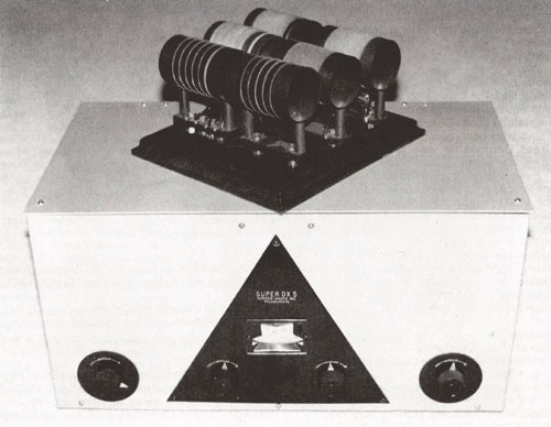
Norden-Hauck Super DX-5
One of a Kind
BY ROBERT E. GRINDER
Robert Grinder shares with R.R.C. readers the tale of collector Les
Rayner's youthful infatuation with the Norden-Hauck Super DX-5 shortwave
receiver, and of Rayner's search for this one-of-a-kind radio. This is a
story with a happy ending.
An earlier version of this paper appeared in the "California Antique Radio Gazette," Volume 16, May 1991, pp 12-15. (Editor)
The saga of the Norden-Hauck Super DX-5 - a
presuperheterodyne, shortwave receiver - is one of the more curious in
the annals of radio manufacturing. This set was marketed but never
manufactured and, apparently, only one prototypical model was
constructed. On the one hand, Norden-Hauck engineers regarded the Super
DX-5 initially as an extraordinary technological marvel. In 1930, they
proudly proclaimed it to be the most advanced shortwave receiver ever!
However, the force of their commitment and the strength of their
enthusiasm succumbed eventually to anguish, disappointment, and
hand-wringing. After declaring in national publications that the Super
DX-5 would be forthcoming soon, NordenHauck engineers recognized that
they had overlooked insurmountable flaws in its design. Consequently,
the Super DX-5 was never manufactured. On the other hand, the engineers
had produced at least one prototypical model of it, which is owned by
Les Rayner of Scottsdale, Arizona.
Les Rayner is well known among collectors of premier
vintage radios. His resources, perseverance, and good luck have enabled
him to assemble an array of rare, relatively early shortwave receivers.
He has possessed, in addition to the NordenHauck Super DX-5, a Pilot
Super Wasp, an ICA Conqueror, a Hammarlund Comet-Pro, a Paragon
RA-10/DA-2, a Grebe CR-18 Special, a Silver-Marshall Around the World
Four, a DeForest Radiophone, a Leutz shortwave receiver, and,
respectively, a National SW-2, SW-3, SW-4, and SW-5.
Les has special affection for the Norden-Hauck Super DX-5. The hyperbole
associated with marketing this receiver in the early 1930s left him
with a lifelong ambition to acquire it. When in the 1970s his desire to
own a DX-5 intensified, he searched vigorously for it. He assumed that
several of the receivers were in private collections.
Fortunately, his industry paid off, for eventually he
obtained a Super DX-5. The significance of his find became apparent when
he realized that the Super DX-5 that he had acquired might be the only
one in existence!
RAYNER'S SEARCH - THE EARLY YEARS
Les Rayner's interest in the world of radio grew
incrementally in the late 1920s. He began tinkering with a few wires and
dry cells, which led him to the radio sections of Popular Science;
later, an Allied Radio Catalog introduced him to the marvel of shortwave
listening. Before long, he convinced his mother that a boy's life
without a shortwave receiver was devoid of meaning. She, in turn, agreed
to advance him funds by which to purchase for $29.50 a Pilot Super Wasp
kit, including tubes and plug-in coils. Since Les' mother worried that
acid from a storage battery might burn holes in her carpets, she
augmented his allowance so that he could buy an A and B battery
eliminator too. During high school, Les advanced to an AC shortwave
receiver - the ICA Conqueror. He read Radio News and Shortwave Craft
avidly because they provided listings and frequencies of stations
throughout the world. The magazines were bursting also with
advertisements for receivers manufactured by Leutz, National, Silver-
Marshall, RCA, etc. But, it was the lesser known engineering company
Norden-Hauck's Super DX-5, shown in Figure 1, that particularly caught
Les' eye .
|
|
|
|
|
|
|
|
|
|
|
|
|
|
|
|
|
|
|
|
Figure 1. The Norden-Hauck Super DX-5.
|
|
|
|
|
|
|
|
|
|
|
|
|
|
Perhaps Les was mesmerized by the relatively compact, aluminum
cabinet, the black, triangular Bakelite panel, or the single, knurled
aluminum drum dial with illuminated celluloid scale. Maybe his interest
was piqued because Norden-Hauck touted the Super DX-5, which covered
from 20 to 205 meters via six plug-in coils, as the most sensitive,
selective, stable, hum-free, and conveniently operated shortwave
receiver on the market. Whatever the reasons, Les began dreaming of
owning a Super DX-5. He did not know its retail price, but he was sure
that it was out-of-reach, for his allowance was too meager ever to make
its purchase possible.
When he reached young adulthood, Les was prompted to
upgrade his ICA. First, he inquired about the availability of the DX-5,
and he learned that production had been suspended. He settled on a
Hammarlund Comet Pro. Shortly thereafter, he finished school, settled
down to married life, embarked upon a career in lithographing, sold the
Comet, and abandoned shortwave listening.
THE LATER YEARS
Forty years later, in the mid-1970s, while shopping in a
Phoenix radio parts store, Les was introduced to the late Bill Pugh,
then one of the more prominent radio collectors on the West Coast. Bill
not only inspired Les to begin collecting vintage radios but rekindled
his interest in searching for the one receiver he still dreamed of
owning - the Super DX-5. For the next 14 years, at national and regional
meets and conventions, Les met prominent collectors from all over the
United States. No one gave him a lead on the DX-5. Eventually, one of
his contacts, John Caperton of Louisville, Kentucky, invited Les to view
his collection of especially rare receivers, and, to, there it sat
inconspicuously on one of John's shelves. For the first time in his
life, Les gazed squarely at a Norden-Hauck Super DX-5. Thereafter,
whenever the two met, Les assured John that he would be a very good
customer, indeed, should he ever decide to sell the DX-5. Clearly
recognizing Les' strong attraction to the set, Caperton sold it to him
early in 1990.
Subsequently, Les traced the DX-5's ownership from
Caperton to Dr. Ralph Muchow, Elgin, Illinois, who, in turn, had
obtained it from an obscure radio technician. Years earlier, the latter
had worked in a laboratory where the DX-5 was undergoing tests, along
with several other receivers. After the tests, he took it home,
apparently because no one else wanted it.
DX-5 CHARACTERISTIC
After searching so assiduously for so many years for the
Super DX-5, and after investigating its features once he had it in his
possession, Les was struck by its incredible uncommonness and rarity.
The DX-5's circuit constitutes a basic regenerative design, and five of
its six tubes are run-of-the-mill, a 227 detector, a 227 first-audio,
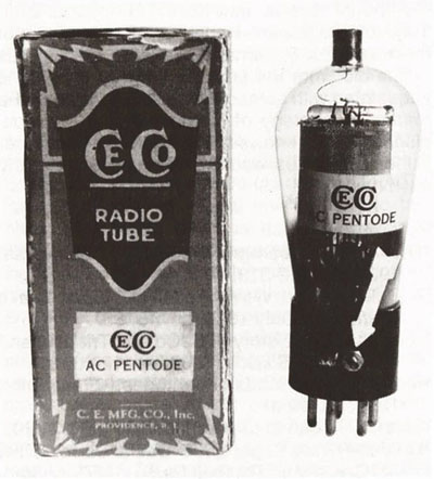
two 245s push-pull audio, and a 280 rectifier. However, the sixth tube
(RF stage) employs the CeCo P1, the first pentode tube developed in the
United States. A Type P-1 tube is shown in Figure 2.
|
|
|
|
|
|
|
|
|
|
|
|
|
|
|
|
|
|
|
|
Figure 2. A CeCo Type P1 tube and it's carton. The arrow points to a tube base connection for the "Space-charge" grid.
|
|
|
|
|
|
|
|
|
|
|
|
|
|
Whereas the typical screen-grid tube provides a capacity shield
around the plate while the inner grid impresses signal input on the
plate, the P-1 provides a second inner, "space-charge" grid with a
positive charge that accelerates the flow of electrons from the
filament. The amplification factor of the P-1 is thus increased.
Indeed, Ernest Kauer, president of CeCo Manufacturing
Co., proclaimed that the P-1 was "three times as powerful as the
screen-grid tube." He neglected to mention that the "space-charge" grid
also introduces enormous inter-element capacity within the P-1. Unless
extensively shielded, the P-1 will couple readily into surrounding
circuitry and destabilize it. As K. Henny noted in Electronics, 1930,
the P-1 grid-plate capacity increases in the same ratio as the gain, so
using it is probably not worth the effort that shielding requires.
Nevertheless, the Norden-Hauck Engineering Co. so
enthusiastically endorsed the P-1 that it seemingly spared no expense to
shield thoroughly the stages of the DX-5. Prospective buyers were
assured in advertisements that, even at the highest frequencies, double,
even triple, shielding guaranteed not only stable operation but also
elimination of the effects of hand capacity on the controls.
Norden-Hauck asserted proudly that workmanship on the
DX-5 was without parallel. No competitor disagreed. None attempted to
match the DX-5, for none believed, apparently, that the P-1 tube was
worth that much effort. According to Alan Douglas, the Super DX-5 was
probably the only receiver ever designed commercially to use the P-1.
CeCo advertised the P-1 in radio magazines during the
first few months of 1930. Adverse publicity followed swiftly, and the
tube was pulled from production about the time it began reaching the
marketplace. Meanwhile, Norden-Hauck, starting in the fall of 1930,
proclaimed the virtues of the P-1 and the Super DX-5 in Radio News,
Short Wave Craft, and OST
Norden-Hauck advertisements never mentioned the price at
which the DX-5 would be sold. Every advertisement exhorted readers to
write the company for "details." Not many readers had the opportunity to
correspond with Norden-Hauck, for, abruptly, it ceased advertising the
Super DX5 in December of 1930.
To this day, Les has no idea what Norden Hauck would have
expected him to pay for a Super DX-5. Even if he could have afforded
one in 1930, he might never have had the opportunity to purchase it. No
evidence exists to confirm that any DX-5 ever made it beyond a test
laboratory to the shelf of a distributor. Norden-Hauck appears to have
realized by late 1930, just as CeCo did a few months earlier, that the
extravagant claims for the P-1 could not be sustained, and, as a
consequence, the hyperbole promoting the DX-5 would not endure.
Although Les did not have the opportunity in 1930 to
write Norden-Hauck for information about the Super DX-5, perhaps someone
reading this article did write the company at that time, or is
acquainted with someone who is familiar with the marketing strategy of
Norden-Hauck. Perhaps, also, someone knows of the existence of another
Super DX-5. Les would appreciate greatly any such news!
References:
"The A. C. Screen-grid Pentode." Radio-Craft,
1930, pp. 512-513.
"A Deluxe Short Wave Receiver." Short Wave
Craft. June/July 1930, pp. 45, 85.
Douglas, A. "The story of CeCo and Triad tubes."
Old Timer's Bulletin, 1980, pp. 12-13, 21.
Henny, K. "Two kinds of pentodes." Electronics,
1930, pp. 40-41.
Kauer, E. "What of the pentode? " Radio, 1930. "Norden-Hauck Super DX-5 Designed for Quiet
AC Operation." Citizens Radio Call Book Magazine and Technical Review, Il, September
1930, p. 52.
(Robert E. Grinder, K7AK, 7735 N. Ironwood Dr., Paradise Valley, AZ 85253)
Robert E. Grinder, a radio amateur since 1946, acquired his first
vintage receiver, still in his possession, over 50 years ago. His
current interests encompass compiling radio directories, writing
historical articles about the radio industry, and restoring and
operating early amateur equipment. His book "The Radio Collector's
Directory and Price Guide," now in its second edition, has long been a
valued reference for collectors.
Antique Radio Classified, APRIL 1997
Pages 8, 9, and 10
|
|
|
|
|
|
|
|
|
|

|
|
|
|
|
|
Click here to learn more about the CeCo P-1 AC Pentode Tube
|
|
|
|
|
|
|
|
|
|
|
|
|

|
|
|
|
|
|
|
|
|
|
|
|
|
|
|
|
This is what my receiver looked like when I first acquired it.
It had years of dust, dirt, and grime inside and out. The front panel
had the loggings of SW stations written all over it and the top lid was
covered with grime and filth.
|
|
|
|
|
|
|
|
|
|
|
|
|
|
|
|
|
|
|
|
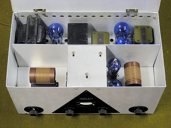
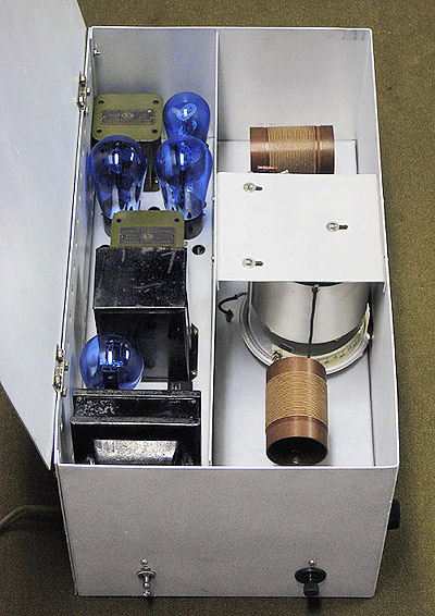
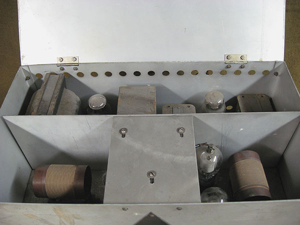
This is what the inside of the receiver looked like with all of
the original tubes that came with it. The power transformer has rust on
the top surface as did the audio transformers to a lesser degree.
|
|
|
|
|
|
|
|
|
|
|
|
|
|
Restoration on this radio was fairly easy. Disassembly was
fairly easy because everything was screwed together with the exception
to some of the tube sockets which were riveted in place. All of the
aluminum was cleaned with Duco's "Navel Jelly" and "Aluminum Jelly" and
several applications were required to each piece in order to completely
eliminate any and all oxidation and staining. The power transformer was
cleaned of any grime and rust that was on it along with the two audio
transformers. The bakelite trim was carefully cleaned with "Simple
Green", rejuvenated with "Old English® Furniture Polish: Scratch Cover
for Dark Wood", and shined with "Guardsman's Furniture Polish". The
engravings were very carefully cleaned out of the original filler and
new filler was applied using "Liquitex" Acrylic paint in an off white
"Parchment" color to more closely replicate the aged color of the
original white filler. The paint is water based so all that need to be
done is to wipe some of it over the engravings and then, after letting
it dry, wiping away the excess with a lightly damp rag. Great care was
taken in handling the bakelite trim because it's only a millimeter thick
and can easily be cracked if handled improperly. The dial was in good
condition but I went ahead and did a dry cleaning of the dial with a dry
cloth since using moist cloth might wind up wiping off the numbers and
scale. All of the screws and hinges were cleaned with "Navel jelly" and
soaked in "Simple Green". Reassembly was fairly easy and straight
forward. The only real challenge was remounting the tuning assembly
which proved to be tricky but not to hard. Care in covering the dial was
exercised when resoldering the various wires back onto the tuning
assembly. Once the receiver was completely reassembled, various
resistors and capacitors were replaced. A CL-90 thermister was installed
in order to protect the transformer from onrush when the receiver is
first turned on. The set now works completely up to it's design.
|
|
|
|
|
|
|
|
|
|

|
|
|
|
|
|
|
|
|
|
This web page was last updated: May 29, 2017
|
|
|
|
|
|
|
|