|
This tube (unlike the British pentode, which has been used as a power
tube only, for the past two years) is designed especially as a
radio-frequency amplifier, to work into tuned-plate impedance; and is
adapted also for audio-frequency amplification in suitable circuits. Its
amplification factor, as may be seen from the technical data given
below, is enormously high; rising to as much as 750, compared with the
420 of the '24 type, which it is intended to replace; while its mutual
conductance may be as high as 2,500, compared with 1,050 for the '24.
This operating characteristic is gained by operating with 250 volts on
the plate, and 135 (positive) on the screengrid; while the space-charge
grid (the new element) carries 20 volts, positive.
It is well known that the older screengrid tubes give two
circuit options. One is that of using the fourth or screen-grid element
as a capacity shield around the plate (from which fact the tube was
often called a "shield-grid" type), while the inner grid serves the
purpose of impressing the signal input on the tube. In the other
connection, the inner grid is used with a positive charge to accelerate
the flow of electrons from the filament and break up the negative "space
charge" which surrounded it. This "space-charge" hook-up is preferred
for audio amplification.
In the new pentode (styled the "P-1" by its manufacturer,
the CeCo Mfg. Co.) both of these advantages are obtainable. We find in
the tube the following:
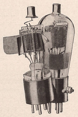
THE FIVE ELECTRODES
(1) A heater filament, similar to that of the '24 type,
drawing 1.75 amperes at 2.5 volts. This is electrically isolated from
the electrodes or elements of the tube, and connected to the "F" prongs
of a UY-type tube base.
(2) An electron-emitter or cathode, heated by the
filament as in the '24 and '27 tubes, and connected to the "C" prong of
the tube.
(3) A "space-charge grid" surrounding the cathode. This
is connected, not to the socket, but to a terminal at the side of the
tube base. To this a source of low, positive potential is connected.
(4) A control-grid which, as in the '22 and '24 types, is
connected to a metal cap at the top of the bulb. This, by means of a
clip and lead, is connected to the signal input:
(5) A screen-grid which, as in previous tube types, is
connected to the "G" prong of the tube base. Upon this is impressed a
high positive voltage, somewhat lower than that of the plate. It serves
the purpose of eliminating the capacitive effect between plate and
control-grid.
(6) A plate, which is similar to that of the '24, and connected to the "P" prong of the tube.
The tube itself, a view of whose elements is given
herewith, fits the standard UY tube socket; it is 1 13/16 inches in
diameter, and 51/4 inches high.
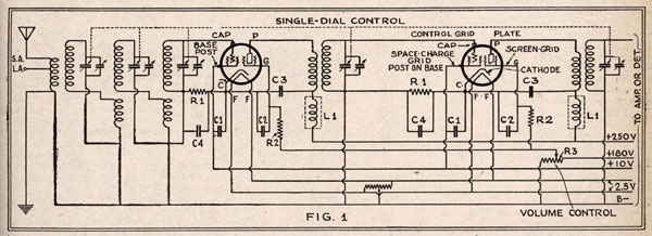
A PENTODE CIRCUIT
The circuit diagram (Fig. 1) given here shows two
pentodes used for R.F. amplification, following a band-pass filter; a
third R.F. stage might follow, or the two stages feed into a standard
detector.
The constants of the coils and tuning condensers are not
given; this would depend upon the design of the receiver. (Articles
dealing with band selectors have appeared, and will appear, in RADIOCent
r from time to time.) The cathode resistors III, producing the
control-grid bias, should be 150 to 160 ohms; the screen-grid resistors
I12, 5,000 ohms; and the potentiometer R3, regulating the voltage on
these elements and thereby serving as a volume control, 25,000 ohms. The
by-pass condensers Cl (for space-charge grid), C2 (for screen-grid), C3
(for plate), and C4 (for cathode) may be of the customary 1-mf. value
each; it will be noted that the common side of the unit shown is the
cathode, or neutral point of the tube, and not the ground. The R.F.
chokes Ll are also of standard value. With the high degree of
amplification obtained by the pentode, the filter system shown is most
essential.
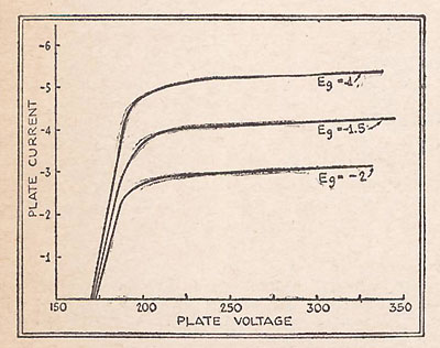
CHARACTERISTICS
In Fig. 2, we illustrate the effect of the various
control-grid voltages upon the plate current. The screen-grid voltage
used is 180 and the space-charge voltage 10. Irrespective of the
control-grid, bias, it will be seen,' the plate-current curve rises
abruptly with the plate voltage until the latter reaches about 180, and
then flattens out.
The curve of the space-charge grid bias, which is not
reproduced here, is practically a straight line, from 7 volts up, under
standard operating conditions. While the increase of this positive grid
voltage results in a higher mutual conductance reading, it produces at
the same time also a higher plate current as well as a much higher grid
current and it is therefore desirable to limit this voltage in the
interests of longer tube life.
A comparison of the P-1 with the '24 type indicates a
comparative R.F. gain 23 per cent higher for the pentode in each stage.
This would amount to 51 per cent more gain for two stages. With such
amplification, it is obvious that precaution against grid overloading
must be taken, especially in the detector. The characteristics of the
tube, with a plate voltage of 250, and a control-grid voltage of 1.5
(negative) are as follows:
|
|