|
|
|
|
|
|
|
|
|
|
|
|
|
|
|
|
|
|
|
|
|
|
|
|
|
|
Silver-Marshall
"Improved Shielded Laboratory
Model
Receiver"
1927
Silver-Marshall Incorporated,
846 W.
Jackson Blvd.,
Chicago, Illinois, USA
|
|
|
| |
|
|
|
|
|
 |
|
|
|
|
|
|
|
|
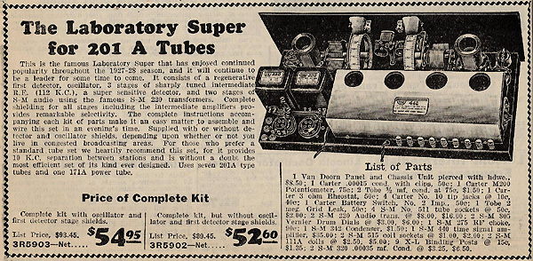
The 1927 Silver-Marshall "Improved Shielded Laboratory Model
Receiver" superheterodyne radio is a well-designed and well-crafted
receiver that performs with excellent reception and great audio
sound. The front end of the set's circuit consists of a
separately tuned oscillator and detector circuit whose tuning dials
turn in opposite directions of each other when tuning in a
station. Both circuits incorporate a regenerative circuit
which is essential for the oscillator but not for the
detector. Regeneration in the detector is adjustable and is
used as an aid in tuning in distant stations. The plug in coil
that's used in both the oscillator circuit and in the detector
circuit is the same in design and consists of three sections of
winding with the third section (feedback winding) being hinged and
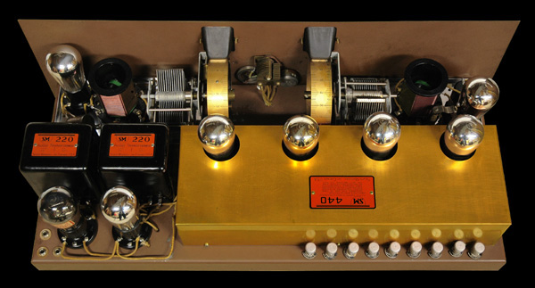
adjustable. The I.F. section, of the receiver, consists of an
enclosed brass box assembly which houses the 1st., 2nd., and 3rd. IF
amplifier stages and the 2nd. detector stage. Each I.F. coil
is wound on a large wooden dowel and coated with paraffin to protect
against moisture. The audio output consists of two,
transformer coupled, audio stages with a 71A amplifier tube driving
the speaker. The front panel is a sheet of metal, in which the
wood grain and central artistic design are printed on, and the steel
chassis is painted flat brown. I acquired this receiver, in
November of 2005, from fellow collector Phil Squire through an abay
auction. |
|
|
| |
|
|
|
|
|
|
Tube Line
Up:
01A...1st. Det.
01A...Oscillator
01A...1st. I.F.
Amplifier
01A...2nd. I.F. Amplifier
01A...3rd. I.F.
Amplifier
01A...2nd. Detector
01A...1st Audio
01A or 12A or
71A...Audio Output |
|
|
| |
|
|
|
|
|
Power
Source:
Battery...+6 Volts
Battery...+45 Volts
Battery...+90
Volts
Battery...+135
Volts
Battery...-4.5
Volts
Battery...-22.5
Volts |
|
|
| |
|
|
|
|
|
Frequency
Range:
BC...550 kHz to 1400 kHz
I.F.Freq...112
kHz |
|
|
| |
|
|
|
|
|
|
|
|
Detentions:
Height...10.5 inches
Width...29
inches
Depth...15.5 inches |
|
|
| |
|
|
|
|
|
|
 |
|
|
|
|
|
Click Here to view the factory
building on Terraserver. The factory is the building just
above the red dot. |
|
|
| |
|
|
|
|
|
|
|
|
|
The schematics and Information for the model 440 I.F.
amplifier unit can be found at the Nostalgia Air web site by
clicking on the link below. |
|
|
| |
|
|
|
|
 |
|
|
|
|
|
Click to this
website to a see a mid 1920s Silver-Marshall radio catalog which
shows a photograph of the factory building. |
|
|
| |
|
|
|
|
|
|
|
 |
|
|
|
|
|
Schematic and
information |
|
|
| |
|
|
|
|
|
|
|
|
 |
|
|
|
|
|
|
|
|
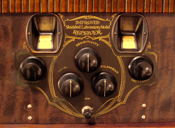
The dial to the left controls the detector, the dial to the right
controls the oscillator, the Gain control regulates the -4.5 volts
supplied to the three I.F. amplifiers, the Sensitive control
regulates the detector's regeneration and the Filament control
regulates all of the tubes filament voltages. |
|
|
| |
|
|
|
|
|
 |
|
|
|
|
|
 |
|
|
|
|
|
|
|
|
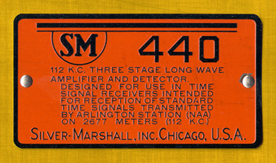
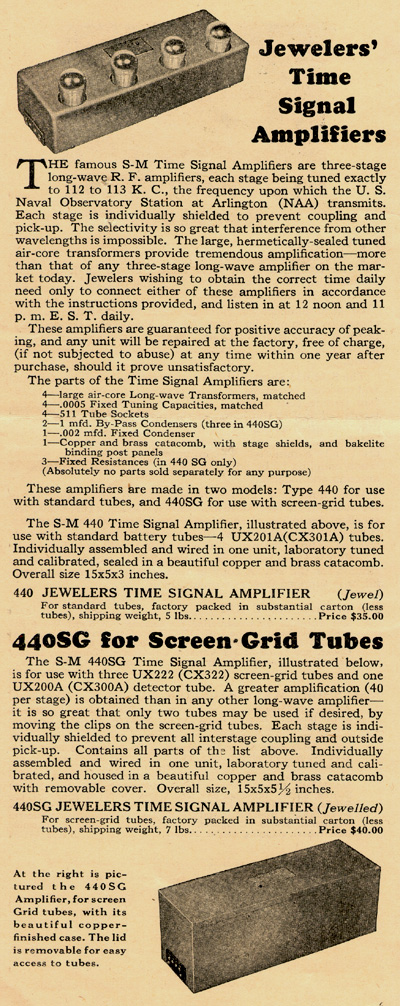
Silver-Marshall could not identify the model 440 as having an I.F.
circuit which could be used in a superheterodyne receiver. To
do so would be in violation of RCA's superheterodyne patents.
To legally get around this, Silver-Marshall described the 440's
circuit as a three stage, long wave, amplifier and detector that was
specifically designed to receive station NAA, on 112 K.C., when the
440 was hooked up as a fixed frequency, TRF, receiver. Most
customers that purchased and used the 440 were well aware of it's
true purpose. |
|
|
| |
|
|
|
|
|
 |
|
|
|
|
|
|
|
|
"Radio"
catalog, 1929 Edition
The Barawik Co.
Chicago, Illinois,
USA
Page 108
|
|
|
| |
|
|
|
|
|
 |
|
|
|
|
|
|
|
|
Silver-Marshall General Parts Catalog
March 15, 1928
|
|
|
| |
|
|
|
|
|
 |
|
|
|
|
|
|
|
|
This was the
exact circuit that my receiver was wired up as.
1928 Rasco
Radio Parts Catalog #18
Page 141
|
|
|
| |
|
|
|
|
|
 |
|
|
|
|
|
|
|
|
|
A second variation of
the standard triod tube set.
|
|
|
| |
|
|
|
|
|
 |
|
|
|
|
|
|
|
|
Wireing
diagram of the second variation, standard triod, tube set.
|
|
|
| |
|
|
|
|
|
 |
|
|
|
|
|
|
|
|
Schematic for the 1928 screen grid tube verson.
Radio News, March
1928
Page 1021
|
|
|
| |
|
|
|
|
|
 |
|
|
|
|
|
|
|
|
Here's a photo, featured on page 1020 of Radio News, March 1928, of
a young girl tuning an "Improved Shielded Laboratory Model"
receiver. Upon close examination, it's shown that the radio
cabinet used is too tall for the radio and a one inch gap exists
between the front panel's decorative upper bar and the
lid. |
|
|
| |
|
|
|
|
|
|
|
|
Electronic
Restoration
The overall performance for this
radio is excellent, a real DXer, and the local stations sound as
good as though they were being received by a 1930s AC radio.
I've been able to achieve this caliber of performance only by doing
a complete electrical restoration on this radio. The first
thing I did was to replace the original gain control. There
was an open in the windings of the 200 ohm filament rheostat
resulting in partial control of the sets gain. After I
replaced it, I examined the detector and oscillator stages, which
seemed to be in good shape, but I chose to go ahead and clean the
tube socket contacts, resolder solder joints and tighten a few
bolted connectors. The I.F. stages were another story.
When I first powered up the receiver, one I.F. tube had an
intermittent filament connection that caused gain to drop at
times. The radio would also go into a locked, runaway,
oscillation whenever the 1st detector's regeneration was run high or
if the set was physically bumped or tapped. The cause of this
problem was found when I carefully opened up the "442" I.F. box and
found that the fixed capacitors on three of the four I.F. coils had
cracked solder joints due to the type of solder that was used and
age. My 35 watt soldering iron wasn't sufficient enough to
solder the connections because the mica capacitors, with their metal
edges, distributed the heat away, too quickly, from the solder
joints for the solder to melt. I resorted to using my micro
butane torch to make the required solder repairs, which it
accomplished perfectly. After I put the cover back on and
mounted I.F. assembly back onto the receiver, normal performance was
achieved. After I ran the set for some time, I determined that
it still didn't quite perform as well as other superheats in my
collection.
After carefully studying the circuit
diagram at some length time, I determined that there were two
original design flaws that prevented this radio from ever achieving
its full potential in performance. The first flaw was in the
circuit of the 2nd detector. It used a negative grid bias setup
and Silver-Marshall chose this for two reasons. First, there
wasn't much room to install a grid capacitor and resistor in the
2nd. detectors small chamber, and second, since the I.F. assembly
was designed to be permanently sealed in a copper box, maintenance
for the grid's capacitor and resistor was near impossible.
Using the negative bias circuit required less components and no
maintenance. Even though the 2nd. detector was sufficiently
sensitive in it's original design; the audio quality was very
poor. I reopened the I.F. assembly and installed a .002 uF
silver mica capacitor with a 1 Meg. metal film resistor into the
grid circuit and, since I had the assembly opened, took to the
liberty of replacing two 0.05 uF bypass capacitors, a 0.003 uF
detector plate bypass capacitor, and I resoldered all of the solder
joints. Once the I.F. assembly was put back together and
installed, I grounded the -4.5 volt wire that connected to the
secondary winding of the 4th I.F. coil. When I had
the set powered up and playing, there was a tremendous improvement
in the sound quality.
The other design flaw I
corrected was in the wiring of the filament control's circuit.
All of the tube filaments were controlled by the filament control,
which worked ok, but every time the control was adjusted, the change
of filament voltage would cause the detector and oscillator to
slightly shift their frequencies. This would require the
retuning of the radio every time the gain was adjusted. Also,
when the filament control was adjusted down because of a strong
local station, the audio output would sound poor and
distorted. To fix this problem, I mounted a 1920s filament
rheostat underneath the chassis, using one of the existing chassis
bolts to secure it, and I rewired the 1st. detector, oscillator, and
two audio output tube filament lines to the rheostat. I
adjusted the rheostat so that with 6 volts supplying the filament
voltage, the selected tubes would receive 4.75 volts each, which
proved very satisfactory in each of the tubes performance. At
this point, only the three I.F. amplifier tubes and 2nd. detector
tube were adjustable. With this setup, the receiver now
performs exactly as one would expect it should. It has
complete control in the 1st. detector's regeneration control, full
control in the filament control with out any negative side effects
and full quality audio output. The set is now ready for
serious competition in an antique radio contest and in general home
use.
|
|
|
| |
|
|
|
|
|
 |
|
|
|
|
|
|
|
|
This web page was last
updated: January 4, 2007
|
|
|
| |
|
|
|