|
1941 Midwest Radio Corporation, 909 - 911 Broadway, Cincinnati, Ohio USA |
||

|
This
chassis features the original factory issued front panel, which is
considered a rare find today. Earlier models of Midwest radios,
such as the 18-35, 18-36, and the 18-37, had chasses that featured a
metal front panel that housed the dial, knobs and escutcheon. The
181, on the other hand, normally didn't feature a front panel and when
the chassis was mounted into one of the various models of Midwest
cabinets, the escutcheon was mounted onto the cabinet itself. In
the case of this receiver, it was originally sold as just the chassis,
speaker and loop antenna; therefore, a front panel was supplied to
provide a surface area for the dial, escutcheon and knobs. This
setup made it easy to have this receiver placed into an older radio
cabinet, custom cabinet, wall or just left as a stand alone
chassis. Earlier 18 tube Midwest radios had large chassis but this
model's chassis is quite compact. The push button tuning is
mechanical. A dial setting is programmed into each push button and
that dial setting is brought up upon the pushing of the button. |
||
|
Tube Line Up: |
||
|
Frequency Ranges: |
||
|
|||||||||
|
Schematic and information |
||

|
This view of the chassis gives a clear indication of how a new chassis looked like just after it's assembly. All of the tubes are Sylvania. |
||

|
This is the instruction and knob identification card that would have been attached on all new Midwest 181 receivers before being shipped from the factory. It was only meant to be a temporary fixture until the owner became familiar with all of the sets knobs and their functions, then it was to be discarded. |
||

|
The Midwest 181 sports a rather large dial measuring 11.5 inches across. The dial is made up in two sections. One section features bands B, C, D, and E which are all printed on a fancy, gold foil, flat background. The other section is the outer curved glass which features the A band. Illumination is accomplished by two dial lamps illuminateing the front surface of the gold background and the rear surface of the curved glass. Because the dial escutcheon is made of Tortoise, the lower portion of the escutcheon illuminates a deep red glow whenever the radio is on. |
||

|
Vol. 25 No. 1 January 1941 Page 32 |
||


|
This is the early version of the 1941 catalog. In this catalog the top of the line chassis features 17 tubes and is referred to as the model VT-17. The VT-17 is electronically the same as the VT-18 minus the 6J5G Audio Level Indicator Level Control. The insert letter is dated October 1, 1940. |
||


|
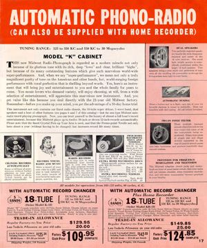
This is the later version of the 1941 catalog. In this catalog the top of the line chassis features 18 tubes and is referred to as the model VT-18 although the VT-17 chassis is still used to illustrate the 18 tube chassis. Also, at this time, the Models K-18 and KR-18, which are housed in the model "K" cabinet, have been added to the line. |
||
|
|
||