|
|
|
|
|
|
|
|
|
|
|
|
|
|
|
|
|
|
|
|
|
|
|
|
|
|
|
|
|
|
Leutz C
1924
Experimenters Information Service,
220 West 42nd. Street,
23 Floor,
New York, New York, USA
|
|
|
|
|
|
|
|
|

|
|
|
|
|
|
|
|
|
|
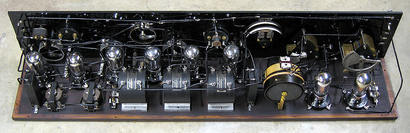
The Leutz model C is a 8 tube superheterodyne receiver, which was
manufactured during the years 1923 and 1924, was designed as a
scaled down version the the earlier model L. There were some changes and
modifications that was done to the model C, while it was on the market,
but the receivers basic design stayed the same. The earlier model Cs
were fitted with RCA UV-1716 IF transformers until RCA stopped selling
them to IES and, subsequently, sued EIS for patent infringements on the
superhet design. EIS responded by designing and manufacturing their own
brand of IF transformers which was named the "Model C Radio Frequency
Transformer". It was a iron core transformer designed to resonate
at 47 kHz and was used extensively in the model C and the later model
C-7.
I purchased this receiver from the late Walter Sanders
estate in 2011. Walt acquired this receiver from an antique mall in Mt.
Horeb, Wisconsin in 1995. I completely disassembled this receiver
down to the nuts and bolts, cleaned and polished everything, repaired
one open IF transformer, replaced one audio transformer, reproduced the
4.5 volt Eveready C bias battery and reassembled everything back
together again.
|
|
|
|
|
|
|
|
|
|
|
|
Tube Line Up:
01A or 00A.....1st. Detector
01A.....Oscillator
01A......1st. Amplifier
01A.....2nd. IF Amplifier
01A.....3rd. IF Amplifier
01A.....2nd. Detector
01A.....1st Audio
01A or 12A.....2nd. Audio
|
|
|
|
|
|
|
|
|
|
Frequency Range:
BC...550 Khz to 1500 Khz
I.F.Freq....47 kHz
|
|
|
|
|
|
|
|
|
|
Power Source:
Battery A.....+6 Volts
B.....+45 Volts
B.....+90 Volts
C.....-4.5 Volts
|
|
|
|
|
|
|
|
|
|
|
|
|
Dementions:
Hight.....40 inches
Wedth.....8 inches
Depth.....8 inches
|
|
|
|
|
|
|
|
|
|
|
|
|
|
|
|
|

|
|
|
|
|
|
Schematic and information
|
|
|
|
|
|
|
|
|
|
|
|
|
|
|
|
|
|
|
|
|
|
|
|
|
|
|
|
|
|
|
|
|
|
|
|
|
|
|
|
|
|
|
|
|
|
|
|
|
|
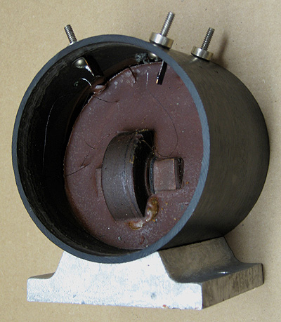
This is what the model C intermediate frequency transformer looks like
from the inside. The promary and secondary coils are wound around an
iron bar and mounted in beeswax. The four contact posts are mearly
screwed in place and can easly become loose causing breakage of the wire
leading to the post. Dissassembly will be required to repair any broken
wires. Some transformers have thier side walls nailed in place but
others only have thier side walls wedged in place. The latter is easier
to open in case repairs are required. A good suction cap may be
suffecient in pulling away the side wall. If the wall is difficult to
remove, freezing it with a freezing spray should reduce it's diameter
just enough to make removal easier. Another method of removing the side
wall is to carefully remove the top ID metal tag and drill a 1/4 inch
hole on the top. Once the hole is made, a rod can be inserted and push
away the side wall. Be careful not to let the drill drop down once it
drills all the way through the shell because it could hit the
windingings of the transformer and do serious damage.
|
|
|
|
|
|
|
|
|
|
|
|
|
|
|
|
|
|
|
|
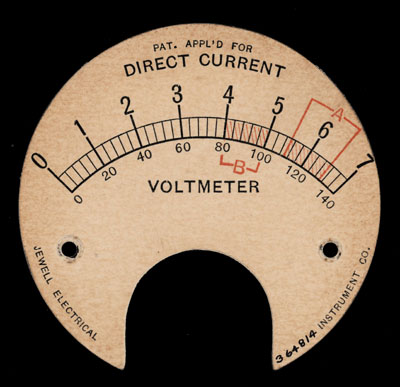
This is the face of the receiver's volt meter. Later versions of the
volt meter featured a five tap switch to monitor the four filiment lines
and one B+ line.
|
|
|
|
|
|
|
|
|
|
|
|
|
|
|
|
|
|
|
|
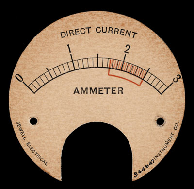
This is the dial face of the receiver's current meter. During proper
operation, the meter's reading should fall within the shaded red area.
|
|
|
|
|
|
|
|
|
|
|
|
|
|
|
|
|
|
|
|
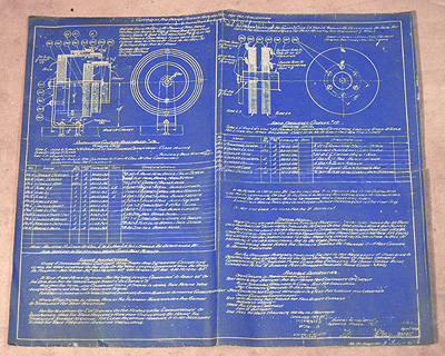
Origional blueprint for the oscillator coil and the 1st. IF coil.
|
|
|
|
|
|
|
|
|
|
|
|
|
|
|
|
|
|
|
|
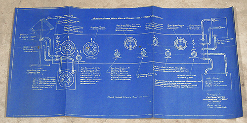
Origional blueprint layout of power and antenna hookup.
|
|
|
|
|
|
|
|
|
|
|
|
|
|
|
|
|
|
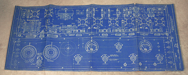
Origional blueprint for the front panel, base board, and the placement of the components.
|
|
|
|
|
|
|
|
|
|
|
|
|
|
|
|
|
|
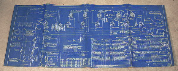
Origional blueprint for the schematic diagram.
|
|
|
|
|
|
|
|
|
|

|
|
|
|
|
|
|
|
|
|
This web page was last updated: November 12, 2017
|
|
|
|
|
|
|
|