|
1934 E. H. Scott Radio Laboratories, Inc., 4450 Ravenswood Ave., Chicago, Illinois, USA |
||

|
The Scott Allwave 15 was introduced in 1934 and was designed to replace the earlier Scott Allwave 12. The added features that the 15 had over the 12 was the addition of a tuning meter driver tube, BFO, and push pull audio driver stage. The audio's output was increased by replacing using a pair of 2A3 in place of 45 tubes. There were two versions of the Allwave 15, an early version which had a 55 2nd detector tube set up as a half wave detector and a late version which had the 55 2nd detector tube set up as a full wave detector. I acquired this set, in 1989 from Norman Braithwait , through a trade with a Scott Worlds Record Shield Grid AC 10. |
||
|
Tube Line Up: Tuner |
||
|
Frequency Ranges: |
||
|
Dementions: |
||
|
Power Source: |
||
|
The schematic for this radio can be found in the Rider manual Vol. XV, Scott Trans. pages 23 to 29. You can also view the schematics and information, of this radio, at the Nostalgia Air web site by clicking on the links below. |
||
|
Click here to view, by means of TerraServer, the location of the factory site as it looks today. |
||
|
Schematics and Information |
||
|
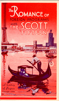
This fold out sales flier measures 5.25 x 3.25 inches. It's one of the more common Scott sales fliers to be found today and regularly pops up on ebay. |
||
|
|
||
|
|
||
|
This Video was created from an original 16mm silent film taken by E. H. Scott himself in 1933 or 1934 at the Scott facility at 4450 Ravinswood, Chicago. The original 16mm film was obtained by Jack Rhodes of Victoria, British Columbia, Canada from the original Scott estate. In 1992 this film was acquired by Jim Clark. It is reproduced here under rights granted by Jim Clark for the benefit of all those that might view and enjoy this historical footage. |
||
|
|
||