|
|
|
|
|
|
|
|
|
|
|
|
|
|
|
|
|
|
|
|
|
|
|
|
|
|
|
|
|
|
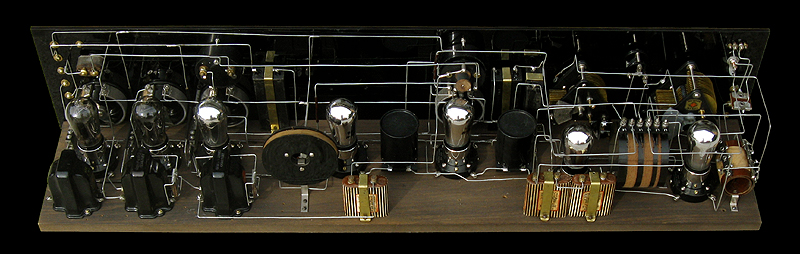
"C. E. Hallen" Leutz C-7
1925
Chicago, Illinois
|
|
|
|
|
|
|
|
|

|
|
|
|
|
|
|
|
|
|
This receiver is believed to have been made by an independent
outfit which was located somewhere within the Chicago vicinity. This
particular receiver is nearly identical to that of the Leutz C-7 except
for the antenna switch, independent filament controls for the audio
stages, an extra power connector which allows the proper bias to be used
for a 71A tube to be used as the final output tube, and the addition of
an impedance matching output transformer for use with cone speakers.
The name "C. E. Hallen" refers to a Carl E. Hallen who
lived at 3852 N. Keeler Ave., Chicago in the Old Ivering Park suburb.
It's not known if he was the builder of this set or a customer who had
his name inscribed onto the panel.
This receiver came from a collection that was auctioned
off by Estes Auctions in early 2017. The two power meters, the second
interstage audio transformer and output transformer, and most of the
audio wiring were missing when I acquired it. The two meters I borrowed
from my Leutz C receiver and I was able to locate two General Radio
model 285 interstage audio transformers and reproduce the wiring. Until I
locate a General Radio model 367 output transformer, I'll have an
unconnected General Radio model 285 interstage audio transformer
occupying it's spot. The entire receiver was dismantled down to every
nut and bolt, cleaned and polished, and carefully reassembled. Even
though this receiver looks complete and functions, it's still in the
process of restoration.
|
|
|
|
|
|
|
|
|
|
|
|
Tube Line Up:
01A or 12A.....1st. Detector
01A.....Oscillator
01A......1st. Amplifier
01A.....2nd. IF Amplifier
01A.....2nd. Detector
01A or 12A.....1st Audio
12A or 71A.....2nd. Audio
|
|
|
|
|
|
|
|
|
|
Frequency Range:
BC...550 Khz to 1500 Khz
I.F.Freq....47 kHz
|
|
|
|
|
|
|
|
|
|
Power Source:
Battery A.....+6 Volts
B.....+45 Volts
B.....+90 Volts
C.....-4.5 Volts
C.....-16.5 Volts
|
|
|
|
|
|
|
|
|
|
|
|
|
Dementions:
Hight.....40 inches
Wedth.....8 inches
Depth.....8 inches
|
|
|
|
|
|
|
|
|
|
|
|
|
|
|
|
|

|
|
|
|
|
|
Schematic and information
|
|
|
|
|
|
|
|
|
|
|
|
|
|
|
|
|
|
|
|
|
|
|
|
|
|
|
|
|
|
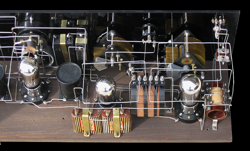
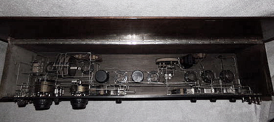
Amplifier
section. The last audio transformer (far left) is supposed to be a
General Radio model 367 output speaker transformer. Right now I just
have a standard General Radio 285 audio transformer occupying the space
where tthe 367 is supposed to be. Until I locate a 367, the 285 will
simply sit there unused.
|
|
|
|
|
|
|
|
|
|
|
|
|
|
|
|
|
|
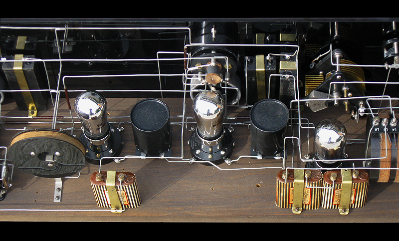
Detector and
IF section. The receiver uses two untuned EIS, plug in, can IF
transformers and one disc shaped tuned IF transformer. The Burgess
battery on the left supplies the -4.5 volt bias to the 1st. and 2nd.
audio tubes. The two Burgess batteries on the right supply the required
-9 volts to the oscillator tube.
|
|
|
|
|
|
|
|
|
|
|
|
|
|
|
|
|
|
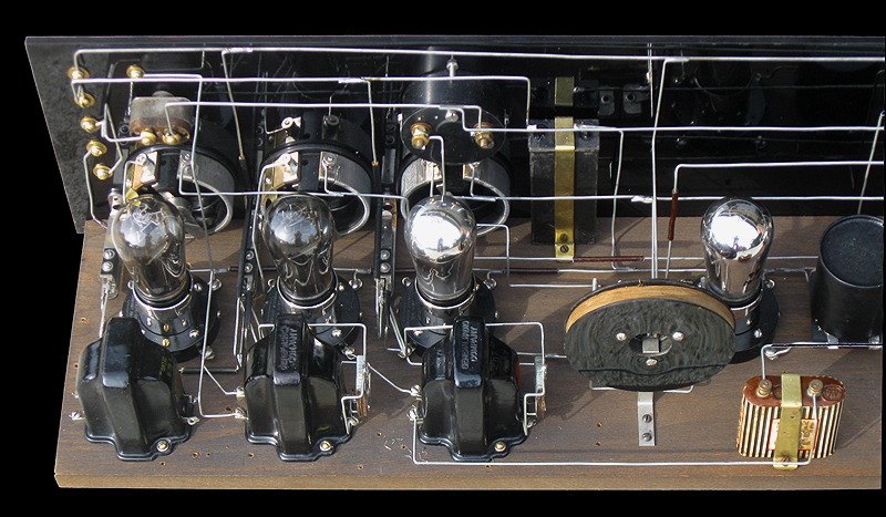
1st.
detector and oscillator section. The large coil, in the center, is the
oscillator coil. The ciol to the far right is the antenna coil.
|
|
|
|
|
|
|
|
|
|
|
|
|
|
|
|
|
|
|
|
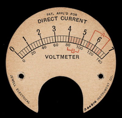
This is the face of the receiver's volt meter. Later versions of the
volt meter featured a five tap switch to monitor the four filiment lines
and one B+ line.
|
|
|
|
|
|
|
|
|
|
|
|
|
|
|
|
|
|
|
|
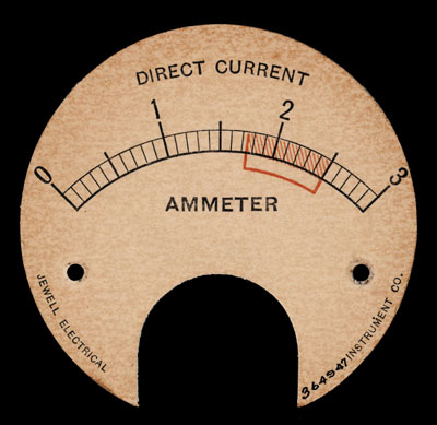
This is the dial face of the receiver's current meter. During proper
operation, the meter's reading should fall within the shaded red area.
|
|
|
|
|
|
|
|
|
|
|
|
|
|
|
|
|
|
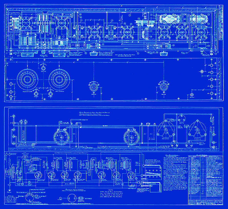
Blueprint for the origional Leutz C-7
|
|
|
|
|
|
|
|
|
|
|
|
|
|
|
|
|
|
|
|
|
|
|
|
|
|
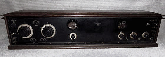
Photos showing the condition of the receiver at the time when it was purchased from the January 2017 Estes Auction.
|
|
|
|
|
|
|
|
|
|

|
|
|
|
|
|
|
|
|
|
This web page was last updated: November 19, 2017
|
|
|
|
|
|
|
|