|
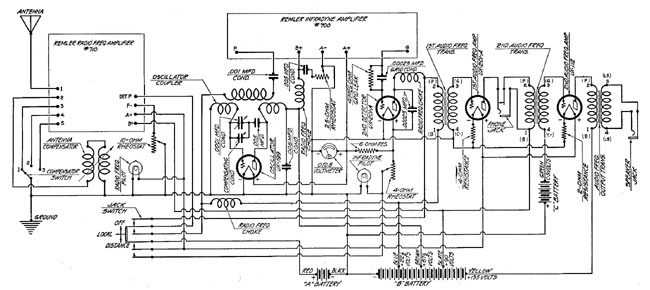
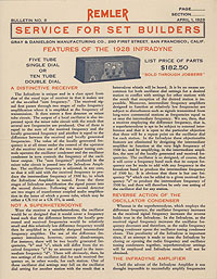
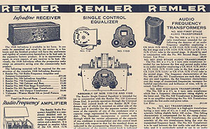
The 1928 Infradyne is a ten-tube receiver in which radio
frequency amplification at broadcast frequencies is combined with
amplification at the relatively high intermediate frequency of 3500 kc.
which is approximately equivalent to a wavelength of 86 meters. In the
intermediate stages the "sum frequency" is amplified. The "sum
frequency" is, as its name indicates, the sum of the received frequency
and a locally generated frequency. Through the use of the sum frequency
selectivity, quiet amplification and freedom from repeat settings on the
oscillator tuning dial are obtained.
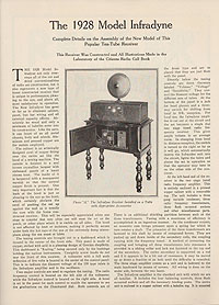
The 1928 Infradyne is particularly distinguished for the
fidelity of its reproduction. For mellowness of tone, for volume without
distortion, it can not be surpassed. Selectivity, which has not been
made so great that side-bands are cut and reproduction is spoiled, is
ample for present day conditions. In locations immediately adjacent to
high-power broadcasting stations fewer distant stations will necessarily
be received during the operation of the local stations than would be
received were the receiver situated in a slightly less congested
locality although no trouble will at any time be experienced in
completely separating local stations.
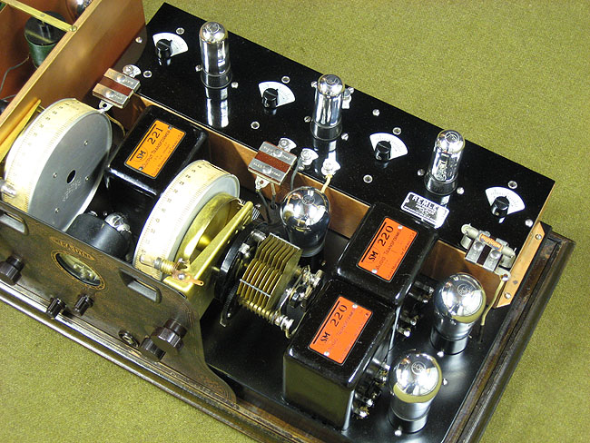
The 1928 Infradyne combines excellent selectivity
and really enjoyable, life-like reproduction with ease of operation,
compactness and attractiveness of appearance. The Infradyne is truly a
universal set which appeals alike to the man who requires the utmost
simplicity of operation and the man who enjoys clear reception of
distant stations. It is housed in a beautiful, sheet-copper cabinet
finished in two-tone brown crystalline enamel which will harmonize
perfectly with the finest of surroundings.
The 1928 Infradyne is provided with a switch having three
positions, "Off," "Local" and "Distance." A turn of this switch to
"Local" brings onto operation a single-dial control, five-tube tuned
radio frequency receiver. When the switch is in the "Distance" position
the complete Infradyne is available.
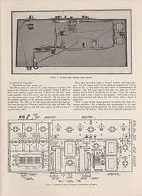
There are but two major tuning dials, one of which
operates the condenser tuning the radio frequency amplifier circuits and
the other of which operates the condenser tuning the local oscillator
circuit. When the panel switch is in the "Local" position and five tubes
only are in use only the tuning dial controlling the radio frequency
amplifier circuits is employed. Each of the two tuning dials rotates
through a full 360 degrees in covering the broadcast band and ample dial
separation of stations is had at all parts of the scale. An adjustment
is provided so that the dials can easily be made to read quite closely
together, with a maximum deviation at the far ends of the scale of
perhaps five or ten degrees. Illumination of the dials is provided and
during the time that five tubes only are in use only the tuning dial
employed will be illuminated. In addition to the tuning dial controls,
volume and sensitivity controls and a filament rheostat are located on
the panel. These controls are all of the semi-fixed type. The volume
control is a rheostat in the filament circuit for the first two radio
frequency tubes and its adjustment determines the gain in the radio
frequency amplifier. The sensitivity rheostat controls the gain in the
intermediate amplifier. The panel rheostat is adjusted so that the panel
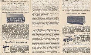
voltmeter reads "3" and is not further used. An "Antenna Compensator"
control is provided. The antenna compensator is a device which nullifies
the detuning effect of the antenna system, making the use of variable
trimmer controls for the radio frequency amplifier unnecessary and hence
simplifying tuning. It permits the immediate adaptation of the receiver
to the particular antenna system used and does not need to be used for
ordinary tuning, once it has been correctly adjusted. Variable coupling
between the primary and secondary circuits of the transformers used in
the radio frequency amplifier is employed and the degree of coupling is
automatically controlled through a cam located on the shaft of the
tuning condenser. The result is that maximum -and uniform gain is
obtained at all wavelengths in the broadcast band.
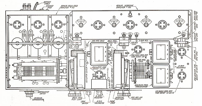
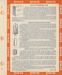
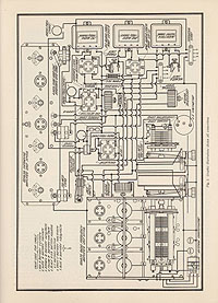
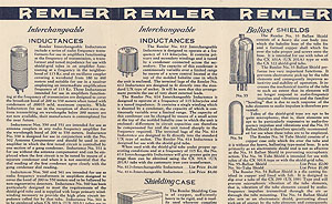
The radio frequency amplifier is a completely shielded,
wired and balanced unit ready for installation in the receiver without
special attention. Switches are provided which can be adjusted at the
time of installation for the degree of selectivity and stability of
operation best suiting the operator and local conditions. Five CX 301A
tubes, four CX 299's and one power tube, which may be either a CX 112 or
a CX 371, are used. These comprise two radio frequency amplifiers
functioning at the frequency of transmission, a first detector or mixer
tube, an oscillator, three intermediate amplifiers functioning at the
fixed frequency of 3500 kc., a second detector and two audio amplifiers.
A six-volt filament supply is required and this should preferably be a
storage battery of 100 ampere-hour or more capacity. Plate voltages of
221/2, 67'/z, 90 and either 135 or 180 are necessary. The plate supply
may consist of "B" batteries of the heavy duty dry-cell type or the
storage type or a suitable "B" eliminator may be used. The Infradyne is
critical as regards filament and plate voltages and the peculiar
requirements of the set must be kept in mind in choosing power supply
devices. The receiver draws a total filament current of two amperes when
the ten tubes are in use and a total current of 1'/z amperes when five
tubes only are being used. The maximum drain on the plate current supply
device, assuming the use in the second audio stage of a CX 371 tube
operated at a plate voltage of 180, will be in the neighborhood of 40
milliamperes. Detailed information regarding the use of "A" and "B"
eliminators with the Infradyne will be supplied upon application.
The Infradyne is, as has been implied in the above
discussion, intended for use with an antenna. One about 40 feet in
length will generally be found about right. In localities far from
broadcasting stations longer antennas can successfully be used and in
localities which are congested as regards broadcast conditions short
antennas of the inside variety can be used with surprisingly good
results.
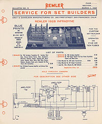
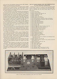
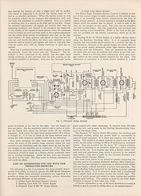
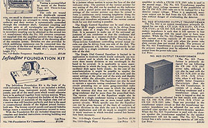
Parts for the 1928 Infradyne are available in kit form.
Six blue prints and a complete and detailed instruction book are
supplied with the No. 750 Foundation Kit. Construction of the set is
simple and virtually resolves itself into the assembly of the component
parts and the installation of a wiring cable laid out by the builder in
accordance with full instructions furnished.
Remler "Service For Set Builders" Bulletin No. 2,
March 1, 1928
|
|